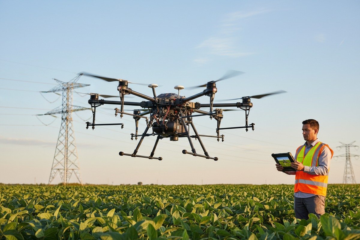
Als unser Produktionsteam die ersten Berichte über GPS-Drift und Kommunikationsausfälle 1 von Landwirten erhielt, die in der Nähe von Sendemasten sprühten, wussten wir, dass dies ein kritisches Problem war. Ein Kunde verlor einen gesamten Sprühzyklus – und Tausende von Dollar –, weil der Kompass seiner Drohne mitten im Flug in der Nähe einer 500-kV-Leitung ausfiel. EMI von Hochspannungsinfrastruktur ist keine bloße Unannehmlichkeit; sie kann Ihren gesamten Präzisionslandwirtschaftsbetrieb lahmlegen.
Um die EMV-Beständigkeit von Agrardrohnen in der Nähe von Hochspannungsleitungen zu überprüfen, müssen Sie auf Konformitätszertifizierungen wie MIL-STD-461 oder EN 61000 achten, Laborprüfberichte anfordern, die die Immunität gegenüber elektromagnetischen Feldern zeigen, interne Abschirmkomponenten inspizieren und kontrollierte Feldtests in der Nähe tatsächlicher Strominfrastruktur durchführen, um eine stabile Flugleistung zu bestätigen.
Dieser Leitfaden führt Sie durch praktische Verifizierungsschritte, vom Verständnis von Prüfzertifikaten über die Bewertung des Hardwareschutzes bis hin zur Zusammenarbeit mit Ihrem Lieferanten an kundenspezifischen Lösungen. Beginnen wir damit, wie Sie bestätigen können, dass Ihre Drohne tatsächlich getestet wurde.
Wie kann ich bestätigen, dass meine Agrardrohne strengen EMI-Beständigkeitstests unterzogen wurde?
Unser Exportteam erhält diese Frage wöchentlich von Distributoren in den USA und Europa. Käufer wollen Beweise, keine Versprechungen. Testberichte von Drittanbietern 2 Die Herausforderung besteht darin, dass viele Hersteller EMI-Resistenz beanspruchen, ohne überprüfbare Dokumentation bereitzustellen.
Um rigorose EMV-Tests zu bestätigen, fordern Sie Testberichte von Drittanbietern an, die sich auf Standards wie MIL-STD-461, RTCA/DO-160 oder EN 61000 beziehen. Suchen Sie nach Daten zu Störfestigkeitsprüfungen, die die Reaktion der Drohne auf abgestrahlte und leitungsgeführte Störungen bei Frequenzen zeigen, die den Netzfrequenzen entsprechen, typischerweise 50-60 Hz Grundfrequenzen mit Oberschwingungen bis 100 MHz und darüber hinaus.

Verständnis wichtiger EMI-Standards
Nicht alle Zertifizierungen sind gleich. Wenn wir Dokumentationen für unsere SkyRover Agrardrohnen vorbereiten, verweisen wir auf spezifische Standards, die für Stromleitungen relevant sind.
| Standard | Fokusbereich | Relevanz für Agrardrohnen |
|---|---|---|
| MIL-STD-461 | Militärische EMV | Höchste Immunitätsstufen; ideal für raue Umgebungen |
| RTCA/DO-160 | Bordausrüstung | Bezieht sich auf die abgestrahlte Störfestigkeit; oft für zivile UAVs erforderlich |
| EN 61000-4-3 | Abgestrahlte Störfestigkeit | Testet die Widerstandsfähigkeit gegen externe HF-Felder |
| FCC Teil 15 | Emissionskonformität | Stellt sicher, dass die Drohne andere Geräte nicht stört |
Worauf Sie in Testberichten achten sollten
Überprüfen Sie bei der Durchsicht von Testdokumenten diese spezifischen Elemente:
- Getesteter Frequenzbereich: Berichte sollten mindestens 10 kHz bis 1 GHz abdecken. Stromleitungen erzeugen Störungen über dieses Spektrum hinweg.
- Feldstärken: Achten Sie auf Störfestigkeitstests bei 10 V/m oder höher. Dies simuliert Bedingungen in der Nähe von Hochspannungsanlagen.
- Testkonfigurationen: Die Drohne sollte im flugbereiten Zustand mit allen aktiven Systemen getestet werden.
- Bestanden/Nicht bestanden-Kriterien: Klare Leistungsschwellenwerte sollten dokumentiert werden.
Fragen an Ihren Lieferanten
Fordern Sie vor dem Kauf Antworten auf diese Fragen an:
- Können Sie den vollständigen EMV-Testbericht bereitstellen, nicht nur ein zusammenfassendes Zertifikat?
- Welches akkreditierte Labor 3 hat die Tests durchgeführt?
- Wurden Tests mit angebrachten Sprühsystemen und Nutzlasten durchgeführt?
- Welche Feldstärken 4 wurden während der Immunitätstests verwendet?
Nach unserer Erfahrung beim Export in die USA vermeiden Käufer, die diese Fragen im Voraus stellen, kostspielige Überraschungen später. Ein Zertifikat ohne unterstützende Daten weist oft auf unvollständige Tests hin.
Rote Flaggen, auf die man achten sollte
Seien Sie vorsichtig, wenn Ihr Lieferant:
- Stellt nur Selbstzertifizierungsdokumente ohne Überprüfung durch Dritte aus
- Kann nicht angeben, gegen welche Standards getestet wurde
- Behauptet "militärische" Schutzwirkung ohne MIL-STD-Dokumentation
- Weigert sich, detaillierte Testparameter weiterzugeben
Auf welche internen Abschirmungsmerkmale sollte ich achten, um meine Drohne vor Hochspannungsstörungen zu schützen?
Wenn wir unsere Flugsteuerungen vor dem Versand kalibrieren, Abschirmkomponenten 5 gehören zu den ersten Dingen, die wir überprüfen. Diese physischen Barrieren sind die erste Verteidigungslinie Ihrer Drohne gegen elektromagnetische Felder, die Sensordaten verfälschen und Kommunikationsverbindungen stören können.
Zu den wichtigsten internen Abschirmungsmerkmalen gehören Metallgehäuse um empfindliche Elektronik, abgeschirmte Verkabelung mit Geflecht- oder Folienwicklungen, leitfähige Dichtungen zum Abdichten von Gehäusespalten, Ferritkerne an Strom- und Datenleitungen sowie Metallgehäuse auf Platinenebene über kritischen Komponenten wie GPS-Empfängern und IMU-Chips.

Arten von Abschirmmaterialien
Verschiedene Materialien bieten unterschiedliche Schutzgrade. Unser Ingenieurteam wählt Materialien basierend auf den Frequenzbereichen aus, die wir blockieren müssen.
| Materialtyp | Frequenzeffektivität | Gewichtseinfluss | Typische Anwendung |
|---|---|---|---|
| Aluminiumgehäuse | Breitband (kHz bis GHz) | Mäßig | Gehäuse der Flugsteuerung |
| Kupferfolienband | 100 MHz bis 10 GHz | Licht | Interne Kabelummantelung |
| Leitfähige Elastomere | DC bis 115 GHz | Sehr leicht | Dichtungen und O-Ringe |
| Ferritperlen 6 | 10 MHz bis 500 MHz | Minimal | Strom- und USB-Leitungen |
| Metallisierter Kunststoff | 1 MHz bis 1 GHz | Licht | Außengehäuse |
Kritische Komponenten, die Schutz benötigen
Nicht jede Drohnenkomponente benötigt eine starke Abschirmung. Konzentrieren Sie Ihre Inspektion auf diese hochpriorisierten Systeme:
GPS/GNSS-Empfänger: Dies ist die EMI-empfindlichste Komponente. Achten Sie auf Metallgehäuse direkt über dem GPS-Modul 7 und abgeschirmte Antennenkabel.
Flugcontroller IMU: Die Inertialmesseinheit enthält Beschleunigungsmesser und Gyroskope. EMI kann zu Sensor-Drift führen. Hochwertige Drohnen platzieren diese in abgeschirmten Gehäusen.
Magnetometer: Der Kompass ist extrem anfällig für Magnetfelder von Stromleitungen. Einige Designs platzieren den Magnetometer auf einem Mast abseits anderer Elektronik.
ESC und Motorverkabelung: Hochstrom-Motorleitungen erzeugen erhebliche EMI. Twisted-Pair-Verkabelung und Ferritkerne reduzieren diese interne Interferenz.
Inspektionscheckliste
Überprüfen Sie diese Punkte bei der Bewertung der Abschirmung einer Drohne:
- Sind die Kabel von Hochstrompfaden weggeführt?
- Haben Gehäusenähte leitfähige Dichtungen?
- Sind sichtbare Ferritperlen an Datenkabeln vorhanden?
- Ist das GPS-Modul sichtbar abgeschirmt?
- Sind Strom- und Signalleitungen getrennt?
Der Kompromiss zwischen Gewicht und Schutz
Landwirtschaftliche Drohnen müssen die Nutzlastkapazität mit dem Schutz in Einklang bringen. Schwere Abschirmungen reduzieren die Flugzeit und das Sprühvolumen. Moderne Lösungen lösen diese Herausforderung.
Leichte RF-absorbierende Elastomere bieten jetzt doppelten EMI- und Umweltschutz. Unsere neuesten Sprühgeräte verwenden co-extrudierte Dichtungen, die 40% weniger wiegen als herkömmliche Kupfergitter und gleichzeitig einen Schutz bis 115 GHz bieten.
Für Landwirte, die in der Nähe von extremen Hochspannungsleitungen (500 kV+) arbeiten, ist der zusätzliche Schutz eine geringfügige Reduzierung der Nutzlast wert. Für Standardbetriebe reicht eine mittlere Abschirmung in der Regel aus.
Wie bewerte ich die Stabilität des Flugreglers, wenn meine Drohne in der Nähe von Stromnetzen betrieben wird?
Unsere F&E-Ingenieure verbringen Wochen damit, Flugsteuerungen in simulierten Freileitungs-Umgebungen zu testen, bevor sie Designs für die Produktion freigeben. Die Flugsteuerung ist das Gehirn Ihrer Drohne – wenn sie ausfällt, fällt alles aus. Die Bewertung ihrer Stabilität erfordert sowohl Laboranalysen als auch reale Verifizierung.
Bewerten Sie die Stabilität des Flugreglers, indem Sie die Spezifikationen des Sensorfusionsalgorithmus überprüfen, die Schwebepräzision in der Nähe bekannter Störquellen testen, Telemetriedaten auf Anomalien bei Kompass und GPS überwachen, auf automatische Notabschaltungen prüfen und Flugprotokolle auf unerklärliche Lageregelungen oder Navigationsfehler während des Betriebs in der Nähe von Stromnetzen analysieren.

Labortestmethoden
Vor dem Feldtest liefert die kontrollierte Laborbewertung Basisdaten. Hier ist, was zu untersuchen ist:
Nahfeld-Scanning: Verwenden Sie magnetische Sonden, um den Rauschboden der Drohne zu ermitteln. Dies identifiziert, welche Frequenzen Probleme verursachen. Spektrumanalysatoren zeigen Interferensspitzen, häufig um 100 MHz von Bordelektronik.
Immunitätskammer-Tests: Setzen Sie die mit Strom versorgte Drohne kalibrierten elektromagnetischen Feldern aus. Überwachen Sie die Sensorwerte auf Drift oder Fehler. Die Drohne sollte bei Feldstärken von 10 V/m oder höher stabile Messwerte beibehalten.
Leitungsgebundene Störungstests: Injizieren Sie Rauschen direkt in Stromleitungen und Datenbusse. Die Flugsteuerung sollte diese Störungen ohne Leistungsverschlechterung filtern.
Feldtestprotokolle
Tests in der realen Welt decken Probleme auf, die Laborsimulationen übersehen. Wir empfehlen diesen strukturierten Ansatz:
| Testphase | Abstand zu den Leitungen | Dauer | Wichtige Beobachtungen |
|---|---|---|---|
| Basislinie | 500+ Meter entfernt | 5 Minuten Schweben | Normale Sensorwerte aufzeichnen |
| Approach | 200 Meter | 5 Minuten Schweben | Auf frühe Anomalien überwachen |
| Nähe | 50-100 Meter | 10 Minuten | Auf GPS-Drift, Kompassfehler prüfen |
| Stresstest | Minimaler Sicherheitsabstand | 15 Minuten | Vollständige Missionssimulation |
Was während der Tests zu überwachen ist
Achten Sie während der Feldtests auf diese spezifischen Parameter:
GPS-Positionsgenauigkeit: Horizontale und vertikale Positionsabweichungen aufzeichnen. Die Werte sollten auch in der Nähe von Stromleitungen innerhalb der Herstellerspezifikationen bleiben.
Kompassausrichtung: Auf plötzliche Sprünge der Ausrichtung oder allmähliche Abweichungen achten. Das Magnetometer ist am anfälligsten für Magnetfelder von Stromleitungen.
Lagestabilität: Roll-, Nick- und Gierwinkel auf unerklärliche Korrekturen prüfen. Die Sensorfusion des Flugreglers sollte stabile Lagendaten beibehalten.
Kommunikationsverbindungsqualität: Beachten Sie Aussetzer der Telemetrie oder Reichweitenreduzierung. HF-Interferenzen von Stromleitungen können Steuerverbindungen beeinträchtigen.
Erweiterte Sensorfusionsfunktionen
Moderne Flugsteuerungen verwenden hochentwickelte Algorithmen, um Interferenzen auszugleichen. Achten Sie auf diese Fähigkeiten:
- Multisensor-Redundanz: Systeme, die GPS-, Kompass-, Barometer- und IMU-Daten abgleichen
- Automatische Sensor-Ausschließung: Fähigkeit, offensichtlich beschädigte Sensoreingaben zu ignorieren
- Adaptive Filterung: Echtzeit-Anpassung der Rauschfilterung basierend auf erkannten Interferenzen
- Visuelle Positions-Sicherung: Kamerabasierte Positionierung, wenn GPS beeinträchtigt ist
Wenn wir Flugsteuerungen für Kunden konfigurieren, die in der Nähe von Umspannwerken tätig sind, aktivieren wir oft erweiterte Filtermodi und reduzieren die Abhängigkeit von Magnetometerdaten während kritischer Flugphasen.
Interpretation von Flugprotokollen
Analysieren Sie nach Testflügen die Protokolle auf folgende Warnzeichen:
- Häufige EKF (Extended Kalman Filter)-Resets
- Kompass-Abweichungs-Warnungen
- GPS-Positions-Sprünge, die 2 Meter überschreiten
- Unerwartete Höhenhaltungen oder Positionskorrekturen
- Motorleistungs-Schwankungen ohne Piloten-Eingabe
Diese Indikatoren deuten darauf hin, dass EMI die Flugstabilität beeinträchtigt, auch wenn die Mission erfolgreich abgeschlossen wurde.
Kann mein Lieferant technische Dokumentation oder kundenspezifisches Engineering bereitstellen, um den EMI-Schutz für meine spezifischen Bedürfnisse zu verbessern?
Wenn Kunden mit einzigartigen operativen Anforderungen auf uns zukommen – wie tägliche Sprühflüge entlang von 500-kV-Übertragungskorridoren – wissen wir, dass Standardlösungen möglicherweise nicht ausreichen. Die Fähigkeit, kundenspezifisches Engineering 9 anzubieten, unterscheidet fähige Lieferanten von einfachen Wiederverkäufern.
Qualitätslieferanten sollten vollständige technische Dokumentationen bereitstellen, einschließlich EMV-Prüfberichten, Abschirmungsspezifikationen und Datenblättern für Komponenten. Sie sollten auch kundenspezifische Ingenieurdienstleistungen anbieten, wie z. B. verbesserte Abschirmungspakete, modifizierte Flugsteuerungsfirmware, spezielle Kabelführungen und die Integration zusätzlicher Filterkomponenten, die auf Ihre spezifische Stromleitungsumgebung zugeschnitten sind.

Dokumentation, die Sie anfordern sollten
Bevor Sie über kundenspezifische Anpassungen sprechen, ermitteln Sie die grundlegenden Fähigkeiten durch Überprüfung der Dokumentation:
| Dokumenttyp | Zweck | Rote Flagge bei Fehlen |
|---|---|---|
| Vollständiger EMV-Testbericht | Immunitätswerte testen | Zeigt unvollständige Tests an |
| Spezifikationen des Abschirmmaterials | Schutzfrequenzbereich verstehen | Schlägt generische Komponenten vor |
| Datenblatt des Flugreglers | Sensordatenblätter prüfen | Macht die Fehlersuche unmöglich |
| Schaltpläne | Qualität der Kabelverlegung beurteilen | Verhindert benutzerdefinierte Modifikationen |
| BMS-Spezifikationen | Funktionen zur Leistungsstabilität bewerten | Wichtig für EMI-Filterung |
Kundenspezifische Engineering-Optionen
Erfahrene Hersteller können Designs für verbesserten EMI-Schutz modifizieren. Hier sind einige Punkte, die Sie mit Ihrem Lieferanten besprechen sollten:
Verbesserte Abschirmungspakete: Zusätzliche Metallgehäuse, verbesserte Dichtungen oder Verlagerung empfindlicher Komponenten weg von störanfälligen Bereichen.
Firmware-Modifikationen: Angepasste Sensorfusionsparameter, verbesserte Filteralgorithmen oder modifizierte Failsafe-Verhaltensweisen für Umgebungen mit hoher EMI.
Hardware-Ergänzungen: Zusätzliche Ferritperlen, Optokoppler zur Vermeidung von Masseschleifen oder verbesserte abgeschirmte Verkabelung im gesamten Flugzeugrahmen.
Batterieintegration: Intelligente BMS-Systeme mit adaptiver Signalfilterung, die trotz EMI-induzierter Welligkeit eine stabile Spannungsausgabe aufrechterhalten. Semi-Festkörperbatterien bieten jetzt eine Energiedichte von 300-400 Wh/kg mit ausgezeichneter EMI-Beständigkeit.
Bewertung der Lieferantenfähigkeit
Nicht alle Lieferanten können kundenspezifische Ingenieursleistungen erbringen. Stellen Sie diese qualifizierenden Fragen:
- Haben Sie eigene Ingenieure oder nur Verkaufsteams?
- Können Sie die Firmware modifizieren oder verlassen Sie sich auf Controller von Drittanbietern?
- Wie lange dauert die Bearbeitung von kundenspezifischen Modifikationen in der Regel?
- Können Sie Beispiele für frühere kundenspezifische EMI-Lösungen liefern?
- Führen Modifikationen zum Erlöschen von Garantien oder Zertifizierungen?
Unser Ingenieurteam in Xi'an arbeitet direkt mit Kunden an kundenspezifischen Projekten zusammen. Dies umfasst die Fernzusammenarbeit bei der Spezifikationsentwicklung und bei Bedarf Vor-Ort-Unterstützung für komplexe Installationen.
Kosten-Nutzen-Analyse
Kundenspezifische EMI-Lösungen beinhalten Kompromisse. Berücksichtigen Sie diesen Rahmen bei Ihrer Entscheidung:
Wenn Standardlösungen ausreichen:
- Betrieb in mehr als 200 Metern Entfernung zu Übertragungsleitungen
- Stromleitungsspannungen unter 220 kV
- Gelegentliche Nähe statt ständiger Exposition
- Einfache Ferritkerne und Standardabschirmung ausreichend
Wann kundenspezifische Entwicklung gerechtfertigt ist:
- Tägliche Einsätze in weniger als 100 Metern Entfernung zu Hochspannungsleitungen
- 500 kV+ Übertragungsinfrastruktur in Sprühzonen
- Frühere Geräteausfälle aufgrund von EMI
- Hochwertige Kulturen, bei denen ein Missionsausfall kostspielig ist
- Versicherungs- oder behördliche Anforderungen für erhöhten Schutz
Zusammenarbeit mit Ihrem Lieferanten
Für erfolgreiche kundenspezifische Projekte:
- Dokumentieren Sie Ihre Betriebsumgebung: Geben Sie Stromleitungsspannungen, Entfernungen und Flugprofile an
- Teilen Sie die Fehlerhistorie: Frühere Vorfälle helfen Ingenieuren, Lösungen zu finden
- Definieren Sie Erfolgskriterien: Geben Sie die akzeptable GPS-Genauigkeit, die Auswirkungen auf die Flugzeit und die Kostengrenzen an
- Planen Sie die Validierung: Stimmen Sie Testprotokolle ab, um Verbesserungen zu überprüfen
- Fordern Sie fortlaufende Unterstützung an: Kundenspezifische Lösungen müssen möglicherweise aufgrund von Erfahrungen im Feld angepasst werden
Die Investition in kundenspezifisches Engineering zahlt sich in der Regel durch reduzierte Missionsausfälle, geringere Kosten für den Austausch von Geräten und zuverlässige Datenerfassung für Präzisionslandwirtschaftsanwendungen aus.
Schlussfolgerung
Die Überprüfung des EMI-Widerstands erfordert einen systematischen Ansatz: Überprüfen Sie Zertifizierungen, inspizieren Sie die Abschirmungshardware, testen Sie die Stabilität des Flugreglers und arbeiten Sie mit Lieferanten zusammen, die Lösungen dokumentieren und anpassen können. Egal, ob Sie ein Händler sind, der für den Wiederverkauf importiert, oder ein landwirtschaftlicher Betreiber, der direkt kauft, diese Verifizierungsschritte schützen Ihre Investition und gewährleisten zuverlässige Präzisionslandwirtschaftsbetriebe in der Nähe von Strominfrastrukturen.
Fußnoten
1. Erklärt häufige Probleme, mit denen Drohnen in der Nähe von Hochspannungsleitungen konfrontiert sind. ︎
2. Betont die Bedeutung der unabhängigen Überprüfung des EMI-Widerstands. ︎
3. Hebt die Notwendigkeit von Tests durch anerkannte und unparteiische Einrichtungen hervor. ︎
4. Definiert die Intensität elektromagnetischer Felder für Immunitätstests. ︎
5. Beschreibt physikalische Barrieren, die die Drohnenelektronik vor EMI schützen. ︎
6. Erklärt, wie diese Komponenten hochfrequente elektronische Störungen unterdrücken. ︎
7. Identifiziert eine kritische Drohnenkomponente, die sehr empfindlich auf EMI reagiert. ︎
8. Beschreibt Softwaremethoden zur Kombination von Sensordaten für Stabilität. ︎
9. Betont maßgeschneiderte Lösungen für einzigartige EMI-Schutzanforderungen. ︎