عندما يقوم فريق الهندسة لدينا بشحن الوحدات من منشأتنا في شيان، نعلم أن اهتزازات النقل يمكن أن تؤدي أحيانًا إلى فك المكونات اهتزازات النقل 1 التي تم معايرتها بشكل مثالي في المصنع. قد يؤدي الفشل في اكتشاف هذه التحولات الدقيقة قبل تخزين أسطولك الجديد إلى فشل كارثي أثناء حالة طوارئ حقيقية، مما يحول أصلًا قيمًا إلى عبء.
لإجراء فحص وظيفي نهائي، والتحقق بشكل منهجي من السلامة الهيكلية، واختبار توازن المحرك والمروحة، وتأكيد محاذاة البرامج الثابتة للبطارية. التحقق من صحة حمولات المهام المحددة مثل الكاميرات الحرارية وعوامل الإطفاء، وضمان تشفير آمن لرابط البيانات، وإجراء اختبار تحويم على ارتفاع منخفض لتأكيد الاستقرار قبل التخزين طويل الأجل.
يضمن هذا المراجعة المنهجية أن تكون معداتك جاهزة للمهمة فور نشرها؛ إليك كيفية تنفيذ كل خطوة حرجة.
كيف يمكنني اختبار استقرار الطيران واستجابة التحكم لطائراتي المسيرة الجديدة؟
أثناء تطوير خوارزميات التحكم في الطيران لدينا، وجدنا أن الاختلافات الطفيفة في التصنيع في آليات قفل الأذرع يمكن أن تسبب اهتزازًا خطيرًا. يجب عليك التحقق من أن الجهاز يعمل كتمديد سلس لإرادة الطيار، بدلاً من محاربة هيكله الخاص.
يتطلب اختبار استقرار الطيران إجراء اختبار تحويم على ارتفاع منخفض للتحقق من الانجراف والتحقق من زمن استجابة رابط التحكم. تأكد من معايرة وحدات القياس بالقصور الذاتي (IMU) ووحدات GPS لمنع أخطاء تحديد المواقع، وتأكد من أن أنظمة تجنب العوائق تتفاعل فورًا مع الحواجز أثناء رحلة الاختبار.

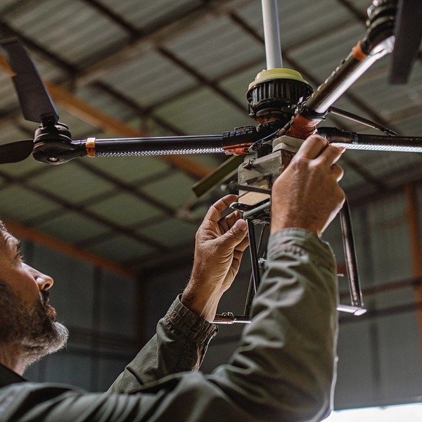
السلامة الهيكلية والقفل الميكانيكي
قبل أن تقوم بتشغيل طائرة الأوكتوكوبتر، يتطلب الهيكل المادي اهتمامًا وثيقًا. طائرات مكافحة الحرائق المسيرة هي منصات رفع ثقيلة، وغالبًا ما تتجاوز 55 رطلاً عند تحميلها بالكامل. الأذرع القابلة للطي، وهي ميزة شائعة للنقل، هي نقاط فشل حرجة إذا لم يتم تأمينها.
ابدأ بفتح جميع الأذرع وتشغيل أكمام أو مشابك القفل. قم بهز كل ذراع بقوة. يجب ألا يكون هناك أي لعب أو "تذبذب" على الإطلاق. إذا اكتشفنا حركة في مفاصل الذراع أثناء مراقبة الجودة في المصنع، يتم رفض هذه الوحدة لأن الاهتزاز هنا يربك وحدة التحكم في الطيران. تحقق من أنابيب ألياف الكربون بحثًا عن أي شقوق دقيقة قد تكون حدثت أثناء الشحن. أنابيب ألياف الكربون 2 قد تبدو الشقوق تجميلية الآن، ولكن تحت عزم الدوران العالي لمهمة مكافحة الحرائق، يمكن أن تؤدي إلى انفصال هيكلي.
معايرة IMU والبوصلة
بمجرد اجتياز الهيكل المادي للفحص، قم بتشغيل الطائرة بدون طيار على سطح مستوٍ. وحدة القياس بالقصور الذاتي (IMU) هي الأذن الداخلية للطائرة بدون طيار. وحدة القياس بالقصور الذاتي 3 وحدة القياس بالقصور الذاتي (IMU) 4 أثناء النقل، يمكن أن يؤدي التداخل المغناطيسي أو الصدمات المادية إلى إزالة معايرة هذه المستشعرات.
قم بتوصيل الطائرة بدون طيار ببرنامج الصيانة الخاص بك أو بتطبيق وحدة التحكم. تحقق من حالة "صحة المستشعر". حتى لو كانت تقول "عادي"، نوصي بإجراء تسلسل معايرة جديد قبل الرحلة الأولى. هذا يضع خط أساس لموقعك المحدد. راقب مستويات تداخل البوصلة؛ إذا كانت تتقلب بشكل كبير أثناء ثبات الطائرة بدون طيار، فقد يكون التدريع الداخلي معطلاً، أو يوجد تداخل مغناطيسي في مستودعك.
فحص صوت المحرك "Idle-Up"
قبل الإقلاع، قم بتسليح المحركات لجعلها تدور بسرعة الخمول. استمع بعناية. لا تحتاج إلى أن تكون مهندس صوت لتسمع المشكلة. يجب أن تصدر جميع المحركات الثمانية همهمة بنفس النغمة بالضبط. يشير صوت الطحن ذو النغمة المنخفضة عادةً إلى وجود محمل تالف أو حطام داخل جرس المحرك. يشير الأزيز ذو النغمة العالية غالبًا إلى عمود مروحة ملتوي قليلاً أو مروحة غير متوازنة.
اختبار التحويم والانجراف على ارتفاع منخفض
قم بإطلاق الطائرة بدون طيار إلى ارتفاع حوالي 2 متر (6 أقدام). اترك عصي التحكم. يجب أن تثبت الطائرة بدون طيار في مكانها. في منشأة اختبار الطيران الخاصة بنا، نبحث عن "الانجرافات الدقيقة" - حركات صغيرة ومتكررة حيث تتجول الطائرة بدون طيار وتصحح نفسها.
إذا دارت الطائرة بدون طيار (على شكل وعاء المرحاض) أو انجرفت بثبات في اتجاه واحد دون رياح، فإن بيانات نظام تحديد المواقع العالمي (GPS) أو البوصلة غير صالحة. ادفع عصي الميل واللف بلطف؛ يجب أن تستجيب الطائرة بدون طيار على الفور وتتوقف بحدة عند تحرير العصي. أي "ليونة" أو تأخير في الكبح يشير إلى أن إعدادات الكسب غير صحيحة أو أن معايرة ESC (وحدة التحكم الإلكترونية في السرعة) خاطئة. وحدة التحكم في السرعة الإلكترونية 5
التحقق من تجنب العقبات
أخيرًا، اختبر مستشعرات الأمان بعناية. اطلب من مساعد حمل لوحة مسطحة كبيرة (لا تستخدم شخصًا أبدًا) والمشي نحو الطائرة بدون طيار المحومة من الأمام والخلف والجوانب. يجب أن تكتشف الطائرة بدون طيار الجسم وتتوقف تلقائيًا على المسافة المحددة مسبقًا (عادةً 2-5 أمتار).
أعطال الاستقرار الشائعة
| العَرَض | السبب المحتمل | الإجراء الموصى به |
|---|---|---|
| الانجراف في نمط دائري | تداخل البوصلة أو سوء المعايرة. | انتقل إلى منطقة خالية من المعادن وأعد معايرة البوصلة. |
| اهتزاز مرئي في تغذية الفيديو | مراوح غير متوازنة أو أقفال أذرع مفكوكة. | أحكم ربط جميع المثبتات الميكانيكية واستبدل المراوح. |
| استجابة فرامل متأخرة | إعدادات كسب منخفضة أو برنامج ثابت قديم. | قم بتحديث البرنامج الثابت وأعد ضبط مكاسب وحدة التحكم في الطيران إلى الوضع الافتراضي. |
| انخفاضات مفاجئة في الارتفاع | خطأ في مقياس الارتفاع أو حساسية للضوء. | تأكد من حماية وحدة التحكم في الطيران من أشعة الشمس المباشرة. |
ما هي الخطوات التي يجب أن أتبعها للتحقق من وظائف نظام حمولة إطفاء الحرائق؟
غالبًا ما نقوم بتخصيص آليات إسقاط للعملاء، وقد تعلمنا أن الأعطال الميكانيكية تحدث عادةً بسبب عدم المحاذاة أثناء الإعداد الأولي، وليس بسبب عيوب في التصميم. التحقق من نظام الحمولة يضمن أنه عند الضغط على الزناد في موقع حريق، يتم نشر العامل بالفعل.
تحقق من وظائف الحمولة عن طريق اختبار وقت استجابة آلية التحرير والتأكد من محاذاة كاميرا الاستهداف مع نقطة الإسقاط الفعلية. تحقق من جميع نقاط التثبيت للتأكد من تثبيتها بإحكام لتحمل الاهتزاز، وتأكد من أن برنامج وحدة التحكم في الطيران يتعرف بشكل صحيح على حمولة عامل الإطفاء المحددة ويقوم بتسليحها.

التفاعل والتوصيل الميكانيكي
تحمل طائرات مكافحة الحرائق عادةً كرات إطفاء، أو خزانات مواد مثبطة للسوائل، أو رشاشات مسحوق جاف. مثبط سائل 6 الخطوة الأولى هي فحص الواجهة بين الطائرة بدون طيار والحمولة.
تحقق من موصلات التحرير السريع. تحمل هذه الطاقة والبيانات. ابحث عن دبابيس ملتوية أو حطام. عند توصيل الحمولة، يجب أن تسمع "نقرة" مميزة أو قفل ميكانيكي. إذا كانت الحمولة تتأرجح، فمن المحتمل أن يتسبب الاهتزاز الناتج عن محركات الطائرة بدون طيار في حدوث خطأ خاطئ في الفصل أثناء الطيران. بالنسبة للخزانات السائلة، افحص الفوهة والخراطيم. يمكن أن تتسبب درجات حرارة الشحن أحيانًا في جفاف الأختام المطاطية أو تشققها. نقترح تشغيل كمية صغيرة من الماء المقطر عبر النظام للتحقق من عدم وجود تسرب قبل تخزينه.
التعرف على البرامج والتسليح
قم بتشغيل الطائرة بدون طيار مع توصيل الحمولة. يجب أن يتعرف جهاز التحكم عن بعد (RC) على الجهاز المحدد على الفور. إذا عرض جهاز التحكم الخاص بك "ملحق غير معروف" أو فشل في عرض واجهة التحكم في الحمولة، فمن المحتمل أن يكون لديك عدم تطابق في البرنامج الثابت.
غالبًا ما تتطلب حمولات مكافحة الحرائق بروتوكولات "فتح" محددة في البرامج لمنع التفريغ العرضي. اختبر هذه الأقفال الآمنة. الأقفال الآمنة 7 على سبيل المثال، حاول تنشيط آلية الإسقاط أثناء وجود الطائرة بدون طيار على الأرض (بدون حمولة فعلية محملة). يجب أن يمنع النظام هذا الإجراء أو يتطلب تأكيدًا محددًا لـ "تسليح الحمولة". إذا سمح النظام بأمر إسقاط دون تأكيد أمان، فهذا يمثل خطرًا أمنيًا يحتاج إلى معالجته بتحديث للبرامج الثابتة.
اختبار تحرير "التشغيل التجريبي"
يجب عليك التحقق من أن محركات السيرفو أو دبابيس التحرير تتحرك فعليًا عند إصدار الأمر. لا تقم بتحميل عوامل إطفاء حية لهذا الاختبار.
- التأكيد البصري: راقب خطاف التحرير أو السيرفو.
- تنفيذ الأمر: قم بتشغيل التحرير من وحدة التحكم.
- فحص زمن الاستجابة: لاحظ الوقت بين الضغط على الزر والإجراء الميكانيكي. في مكافحة الحرائق، يعني تأخير نصف ثانية تفويت نافذة الهدف. يجب أن تكون الاستجابة فورية تقريبًا.
- إعادة الضبط: تأكد من عودة الآلية إلى الوضع "المغلق" بسلاسة. إذا علقت، قم بتطبيق مادة تشحيم غير موصلة يوصي بها الدليل.
محاذاة كاميرا الاستهداف
تأتي معظم حمولات الحرائق مع كاميرا مخصصة موجهة للأسفل للتصويب. يجب محاذاة هذه الكاميرا مع مسار الإسقاط الفعلي.
ضع علامة هدف على الأرض. قم بتحويم الطائرة بدون طيار فوقها مباشرة باستخدام عرض كاميرا الاستهداف. قم بإنزال الطائرة بدون طيار بالضبط حيث تعتقد أن الهدف موجود. بعد ذلك، قم بقياس المسافة فعليًا بين مركز آلية إسقاط الطائرة بدون طيار وعلامة الهدف. إذا كان الانحراف كبيرًا (أكثر من 10-15 سم)، فستحتاج إلى ضبط حامل الكاميرا أو إجراء معايرة إزاحة برمجية. الكاميرا غير المحاذاة تجعل الطائرة بدون طيار عديمة الفائدة لكرات الإطفاء الدقيقة.
نقاط فحص نظام الحمولة
| مكون الفحص | ما الذي تبحث عنه | عواقب الفشل |
|---|---|---|
| دبابيس الموصل | طلاء الذهب سليم، لا يوجد انحناء، لا يوجد تآكل. | فقدان إشارة التحكم إلى الحمولة؛ فشل في الإسقاط. |
| خراطيم خزان السائل | تشققات، هشاشة، مشابك مفكوكة. | تسرب مثبط على المكونات الإلكترونية (دائرة قصر). |
| محركات السيرفو | حركة سلسة، لا يوجد صوت "طحن". | تعطل الحمولة؛ عدم القدرة على إطلاق المادة. |
| دبابيس الأمان | علامات الإزالة قبل الطيران مرئية وسليمة. | تفريغ عرضي أثناء النقل أو الإعداد. |
كيف يمكنني التحقق من عمر البطارية وقدرة الطيران الفعلية مقابل المواصفات؟
يقوم موردو البطاريات لدينا بتحسين كثافة الطاقة باستمرار، لكننا لا نزال نرى تباينات في الأداء إذا تم تخزين الخلايا بشكل غير صحيح أثناء التوزيع. لا يمكنك الاعتماد فقط على الملصق المطبوع؛ يجب عليك التحقق من الصحة الكيميائية لمصدر الطاقة قبل الوثوق به في مهمة.
تحقق من عمر البطارية عن طريق إجراء اختبار طفو كامل بأقصى وزن للحمولة لقياس وقت التفريغ الفعلي مقابل المواصفات المقدرة. راقب جهود الخلايا الفردية للتأكد من اتساقها تحت الحمل، مع التأكد من عدم حدوث انخفاض في الجهد، وتحقق من أن وضع التخزين لمحطة البطارية يعيد الخلايا بنجاح إلى مستويات آمنة للتخزين.

الفحص المادي للبطاريات الذكية
ابدأ بفحص بصري لكل حزمة بطارية. البطاريات عالية السعة من نوع ليثيوم بوليمر (LiPo) أو البطاريات الصلبة المستخدمة في هذه الطائرات بدون طيار متطايرة. ابحث عن أي انتفاخ أو تورم. حتى التورم الطفيف يشير إلى تراكم الغازات الداخلية بسبب تدهور الخلية، ويجب رفض هذه البطاريات على الفور.
افحص موصلات الطاقة الرئيسية (غالبًا AS150 أو موصلات مماثلة مضادة للشرر). يجب أن تكون نظيفة وخالية من تراكم الكربون (علامات سوداء)، مما يشير إلى حدوث شرر من التوصيلات السابقة. تأكد من أن البطارية تنزلق في حجرة بطارية الطائرة بدون طيار بسلاسة وتثبت بإحكام. يمكن أن تنفصل البطارية غير المثبتة أثناء المناورات عالية الجاذبية، مما يتسبب في سقوط الطائرة بدون طيار من السماء.
محاذاة البرامج الثابتة
تحتوي البطاريات الصناعية الحديثة على معالجات داخلية خاصة بها. عند توصيل البطارية بالطائرة بدون طيار أو محطة الشحن، تحقق من إصدار البرنامج الثابت. يعد البرنامج الثابت غير المتطابق للبطارية سببًا شائعًا لأخطاء إدارة الطاقة. إذا كان البرنامج الثابت للبطارية أقدم من البرنامج الثابت لوحدة التحكم في الطيران للطائرة بدون طيار، فقد تخطئ الطائرة بدون طيار في حساب وقت الطيران المتبقي، مما يؤدي إلى هبوط قسري.
اختبار التحميل واتساق الجهد
الطريقة الوحيدة للتحقق حقًا من القدرة على التحمل هي اختبار الطفو تحت الحمل.
- الشحن الكامل: اشحن البطارية إلى 100%.
- إضافة وزن: قم بتوصيل حمولة وهمية تعادل الحد الأقصى لوزن الإقلاع (MTOW).
- الطفو: قم بتعليق الطائرة بدون طيار على ارتفاع آمن (2 متر).
- المراقبة: راقب جهد الخلية على شاشة وحدة التحكم.
يجب أن تستنزف جميع الخلايا بنفس المعدل. إذا كانت الخلية 1 عند 3.8 فولت وانخفضت الخلية 4 إلى 3.5 فولت بسرعة، فهذا يعني أن لديك "خلية سيئة". سيؤدي هذا الخلل في التوازن إلى تشغيل تحذير انخفاض البطارية المبكر. سجل وقت الطيران الإجمالي حتى تصل البطارية إلى 15%. قارن هذا بالمواصفات الفنية للشركة المصنعة. يعتبر الاختلاف بنسبة 10-15% طبيعيًا اعتمادًا على الظروف البيئية (الرياح، درجة الحرارة)، ولكن انخفاضًا بنسبة 30% يشير إلى بطارية معيبة.
اختبار "وضع التخزين"
نظرًا لأنك تفحص هذه الطائرات بدون طيار قبل التخزين, ، فإن اختبار قدرة التفريغ لا يقل أهمية عن اختبار الشحن. تتحلل بطاريات LiPo المشحونة بالكامل وتنتفخ إذا تم تخزينها لأكثر من بضعة أيام.
ضع البطاريات الكاملة في محطة الشحن الذكية وحدد "وضع التخزين". يجب على المحطة تفريغ البطاريات إلى سعة تتراوح تقريبًا بين 40-60% (عادة حوالي 3.80 فولت إلى 3.85 فولت لكل خلية). تحقق من أن هذه العملية تعمل وأن البطاريات تتوقف عن التفريغ عند المستوى الصحيح. إذا فشلت المحطة في تفريغها، فلا يمكنك تخزين الأسطول بأمان.
سجل بيانات صحة البطارية
| متري | النطاق المقبول | العلم الأحمر |
|---|---|---|
| انحراف جهد الخلية | فرق < 0.05 فولت بين الخلايا. | فرق > 0.1 فولت تحت الحمل. |
| جهد الشحن الكامل | 4.20 فولت (LiPo) أو 4.35 فولت (LiHV) لكل خلية. | الفشل في الوصول إلى الجهد الأقصى. |
| المقاومة الداخلية | عادةً < 5-10 ملي أوم لكل خلية. | > 15-20 ملي أوم (يشير إلى التقادم). |
| درجة الحرارة | 30 درجة مئوية – 40 درجة مئوية بعد الرحلة. | > 60 درجة مئوية (يشير إلى إجهاد مفرط). |
ما هو الإجراء الصحيح للتحقق من جودة الكاميرا الحرارية ونقل البيانات؟
في تجربتنا في التصدير إلى الأسواق العالمية، نجد أن التداخل المحلي للترددات الراديوية يمكن أن يؤثر بشدة على بث الفيديو، وهو أمر لا يمكن للاختبارات المصنعية محاكاته بالكامل. تحتاج إلى التأكد من أن عيونكم في السماء تظل واضحة وحادة، حتى عندما تكون البيئة الكهرومغناطيسية معادية.
تحقق من الكاميرات الحرارية عن طريق توجيهها إلى أجسام ذات فروق درجات حرارة معروفة للتحقق من دقة المستشعر ومعايرة اللوحة. في الوقت نفسه، قم بمراجعة بث إرسال الفيديو بحثًا عن التأخير أو التشوهات عند أقصى مسافة تشغيل، وتأكد من أن رابط البيانات يظل مشفرًا ومعزولًا عن الشبكات العامة غير المصرح بها.

معايرة المستشعر الحراري والتحقق من اللوحة
تعتمد طائرات مكافحة الحرائق بدون طيار على الكاميرات الحرارية الإشعاعية لتحديد النقاط الساخنة. الكاميرات الحرارية الإشعاعية 8 لاختبار ذلك، تحتاج إلى بيئة "معروفة".
قم بإعداد مشهد بأجسام ذات درجات حرارة متباينة: دلو من الماء المثلج، وشخص، ومصدر حرارة (مثل سخان فضاء).
قم بتشغيل الكاميرا وقم بالتبديل إلى الوضع الحراري.
- فحص الدقة: استخدم وظيفة "مقياس البقعة" للنقر على الشخص. يجب أن يقرأ حوالي 97 درجة فهرنهايت - 99 درجة فهرنهايت (36 درجة مئوية - 37 درجة مئوية). إذا قرأ 120 درجة فهرنهايت أو 60 درجة فهرنهايت، فإن إعدادات الانبعاثية خاطئة أو أن المستشعر غير معاير.
- فحص اللوحة: قم بالتبديل عبر لوحات الألوان المختلفة (الأبيض الساخن، الأسود الساخن، قوس الحديد). في عمليات مكافحة الحرائق، تعتبر "المتساوي الحرارة" أمرًا بالغ الأهمية - تأكد من أنه يمكنك تعيين إنذار درجة حرارة محدد (على سبيل المثال، عرض كل شيء فوق 300 درجة فهرنهايت باللون الأحمر).
- تصحيح المجال المسطح (FFC): قم بتشغيل معايرة FFC (عادةً ما يكون صوت نقر). يجب أن تتجمد الصورة للحظة ثم تزيل أي "ضوضاء" أو حبيبات.
استقرار إرسال الفيديو
رابط الفيديو (شبكات OcuSync أو Lightbridge أو شبكات شبكية خاصة) هو شريان حياتك. يصعب اختبار ذلك في مستودع بسبب ارتداد الإشارة، لذا نوصي بإجراء اختبار في الهواء الطلق بخط رؤية مباشر.
قم بالمشي بالطائرة بدون طيار (أو قم بتطيرها) إلى مسافة معقولة. راقب زمن استجابة بث الفيديو. لوّح بيدك أمام الكاميرا وشاهد الشاشة. يجب أن يكون التأخير غير محسوس (أقل من 200 مللي ثانية). إذا كان الفيديو يتقطع أو يتجمد أو يتشوه (تكتل) على مسافة قصيرة، فتحقق من توصيلات الهوائي على كل من الطائرة بدون طيار ووحدة التحكم. تأكد من توجيه الهوائيات بشكل صحيح (الجانب المسطح مواجه للطائرة بدون طيار).
أمان وتشفير رابط البيانات
بالنسبة لعقود الحكومة وإدارات الإطفاء، يعد أمان البيانات أمرًا بالغ الأهمية. يجب عليك التحقق من أن الطائرة بدون طيار لا تبث إشارة Wi-Fi مفتوحة يمكن للجمهور الوصول إليها.
تحقق من إعدادات الإرسال في التطبيق. تحقق من تمكين تشفير AES-256 (أو المعيار المحدد الذي تتطلبه إدارتك). تشفير AES-256 9 حاول مسح بث فيديو الطائرة بدون طيار باستخدام هاتف ذكي قياسي أو وحدة تحكم ثانوية غير مقترنة. يجب عليك لا أن تكون قادرًا على رؤية البث. أيضًا، تحقق من "الوضع غير المتصل". تتطلب العديد من إدارات الإطفاء أن تعمل الطائرات بدون طيار دون الاتصال بخوادم سحابية الشركة المصنعة. ضع الجهاز اللوحي في وضع الطائرة وتأكد من أن الطائرة بدون طيار لا تزال تعمل بالكامل دون طلب تسجيل دخول أو اتصال بالإنترنت.
فحص ختم الحماية من الدخول (IP)
أخيرًا، افحص الأختام المادية التي تحمي الإلكترونيات. الأختام المادية 10 تعمل طائرات الإطفاء بدون طيار في بيئات مليئة برذاذ الماء والسخام والرماد.
تحقق من الحشوات المطاطية التي تغطي منافذ USB وفتحات بطاقة SD. يجب أن تكون مستوية ومحكمة. افحص فتحات التبريد. غالبًا ما تستخدم طائرات الإطفاء الاحترافية مرشحات شبكية لمنع الجسيمات الكبيرة. إذا كانت هذه المرشحات ممزقة أو غير محاذية، يمكن أن يدخل غبار الكربون الموصل من الحريق إلى الجسم ويؤدي إلى قصر الدائرة في اللوحة الرئيسية.
قائمة فحص الفيديو والمستشعرات
| عنصر الاختبار | الإجراء | معايير النجاح |
|---|---|---|
| دقة مقياس البقعة | قم بقياس جسم ذي درجة حرارة معروفة. | التباين ضمن ±2 درجة مئوية أو ±2%. |
| ثبات المحور | هز الطائرة بدون طيار بلطف أثناء التشغيل. | يبقى الفيديو مستويًا تمامًا؛ لا يوجد طنين. |
| زمن استجابة الإرسال | اختبار تلويح اليد. | تأخير أقل من 200 مللي ثانية؛ لا يوجد تجميد. |
| حالة التشفير | تحقق من قائمة الإعدادات. | "AES-256 ممكّن" / "مفتاح مخصص نشط". |
الخاتمة
إن إجراء فحص وظيفي نهائي صارم قبل تخزين طائرات مكافحة الحرائق الخاصة بك ليس مجرد وضع علامات على مربعات؛ بل يتعلق بضمان سلامة موظفيك والجمهور. من خلال التحقق المنهجي من الاستقرار وآليات الحمولة وصحة البطارية ودقة المستشعرات، فإنك تضمن أنه عندما يدوي الإنذار، فإن تقنيتك تعمل بشكل لا تشوبه شائبة. بصفتنا مصنعًا، فإننا ندعم هندستنا، لكننا نعتمد على اجتهادك في هذه المرحلة النهائية للحفاظ على أعلى معايير الجاهزية التشغيلية.
الحواشي
1. ASTM D4169 هو المعيار الصناعي لاختبار حاويات الشحن ضد اهتزازات النقل. ︎
2. نظرة عامة على خصائص مادة ألياف الكربون وتطبيقاتها الهيكلية. ︎
3. معيار IEEE للمصطلحات وطرق اختبار المستشعرات بالقصور الذاتي. ︎
4. توفر MathWorks وثائق فنية موثوقة حول وظيفة وتطبيق مستشعرات IMU. ︎
5. خلفية عامة حول وظيفة ومعايرة وحدات التحكم الإلكترونية في السرعة في الطائرات بدون طيار. ︎
6. خدمة الغابات الأمريكية هي السلطة الأساسية لمواصفات واستخدام مثبطات الحرائق الجوية. ︎
7. ISO 14119 هو المعيار العالمي لأجهزة التشابك الآمنة المرتبطة بحواجز الآلات. ︎
8. شرح تقني للتصوير الحراري الإشعاعي من شركة مصنعة رائدة. ︎
9. NIST FIPS 197 هو المعيار الحكومي الرسمي الذي يحدد معيار التشفير المتقدم (AES). ︎
10. شرح اللجنة الكهروتقنية الدولية لتصنيفات IP لحاويات الإلكترونيات. ︎